Rain Display
I don't remember how I originally came up with the idea for this project, but it sure ended up being quite a process. I wanted to make something as a playful commentary about all the rain where I live, and I wasn't initially sure how I would go about that. In the end it turned out to be rather complicated, and I had to learn a variety of new electronics and serial data skills to pull it off. The project uses two components; the LED matrix display and the sensor/transmitter, both of which use AVR microcontrollers as their brains. While I've since made similar projects based on AVR microcontrollers, this was my first one, so I used Arduino boot loaders on both devices to cut down on the learning curve.
Code for both components can be found on my GitHub repository here.
 The display component
 The dectector/transciever component
Parts List
should you be interested in making something similar for yourself, here is a shopping list of components used. These parts are most conveniently gotten from online retailers like Sparkfun, and Solarbotics.
Display Components
- Atmega 328p This is the same chip that the Arduino Uno uses. If you're willing to play with your Arduino IDE, you could use a comparable chip with fewer I/O pins, etc. If you bought this chip, it likely did not come with the Arduino bootloader burned to it. You'll need that to use arduino commands, and I refer you to this tutorial. If (like me) you've never been able to upload code to an AVR chip with ArduinoISP from the IDE, this tutorial has directions for doing it from the command line.
- Max7219 LED driver This chip can be used in one mode to drive 7-segment alphanumeric LEDs, or, as in our case, matrix display mode. Can drive up to 84 LEDs.
- Voltage regulator Step power down from 9v input to 5v output. I highly recommend you get a switching regulator like this one. A cheap linear regulator will just drink your batteries.
- 10uf capacitor
- 9 volt battery snap connector Or like a case and leads for AA batteries, whatever you want to use. A barrel connector if you were using a wall wart would also be a great option. These keep the power supplied to the MCU nice and noise free.
- Lots of LEDs I used a display of 8 rows and 7 columns, so 56 leds, but there's no reason it couldn't be a 8 x 8 display, or whatever. Get a pack of 100 5mm LEDs.
- Resistors I used a 10k Ohm resistor on the Atmega's reset pin, and something like 540 Ohms to set the LED voltage on the Max7219. See this article about building an arduino on a breadboard for a further explanation.
- An RF link receiver Like this one.
Chips
Power Supply Stuff
Other components
Sensor Components
- Attiny 85 This is the brains of the sensor. You will have to play with your Arduino IDE to use Arduino commands with the attiny85. This site has all the info to help you out.
- The same 10uf cap, voltage regulator and battery snap in the display listing.
- Piezo element Used to detect the vibrations from rain drops. This triggers a transmission. Check out this instructable to give yourself a better idea of what this is for.
- Resistor A 200 Ohm resistor or thereabouts between the leads of the piezo keeps the signal nice and clean. You may find this optional, so try it on a breadboard.
- An RF link transciever Like this one.
Chip
Power Supply Stuff
Other Components
Naturally, a few other things were needed, not the least of which is acrylic sheeting to make the enclosure for the display. There is a plastic shop near my home where I was able to get off cuts for cheap. I used a bit of white sheet, as well as transparent.
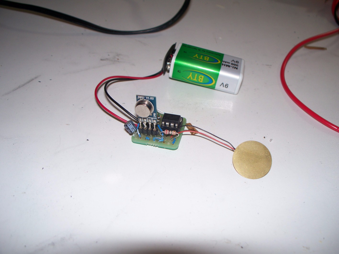
Obviously some wire and protoboard were used to build the circuits. I was very proud of getting my sensor to fit on this adorable protoboard.
How it works
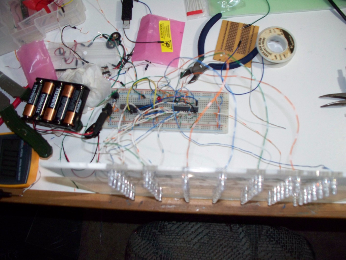
I wish I took more pictures of the breadboarding, but this blurry one is the best I have. There's not a lot you can tell from the image, but you can get a sense of how many connections there are, and why it's important to try it out on a breadboard first.
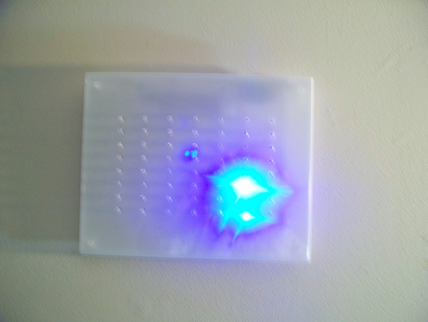
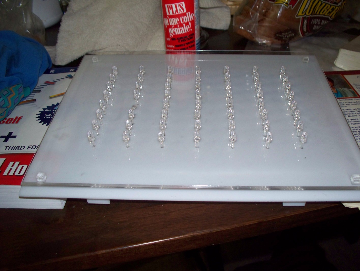
The acrylic sheet with the LEDs was intended to be the display, but I decided it looked ugly, and made something better.
The Software
This project started as a very abstract idea, and my plans involved many revisions to both the software and the electronic componenets. In the end, the device worked as so:
- The sensor component waits around with the piezoelectric element expoxy glued to some surface that will vibrate every time a rain drop hits it.
- Upon detecting the vibration, the Attiny 85 goes into an interrupt state and sends a message via serial data over radio frequency. How this works is discussed a bit further down.
- Upon receiving the serial data message, the display sends an LED chase sequence down a pseudo-randomly selected column, simulating a little rain drop.
I don't want to get too geeky with how this all works; this probably isn't the place to discuss microprocessor interrupt routines, etc.
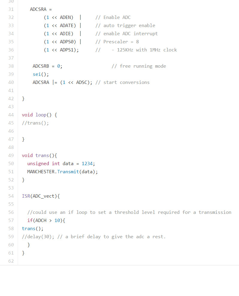
Here's a code snippet from the sensor. A few things to note are that I used lots of non-Arduino AVR bit setting (e.g. 'ADCSRA = ...'), and in the trans() function notice that the only message sent is '1234'. After all, it doesn't matter what message is actually sent as the display is only considering whether or not a message has been received without regard to the content. A similar setup could be used to send/receive whatever serial data is required, even something complex.
The serial protocol I'm using is called Manchester encoding, which I chose in part because the library is quite straightforward, and because the protocol is very forgiving of slight timing changes in between the sender and receiver as one would expect if the sensor was outside and very cold while the receiver was much warmer.
I did not create the Manchester library and credit belongs to GitHub user mchr3k. You can find the library here. It really is a very cool library.
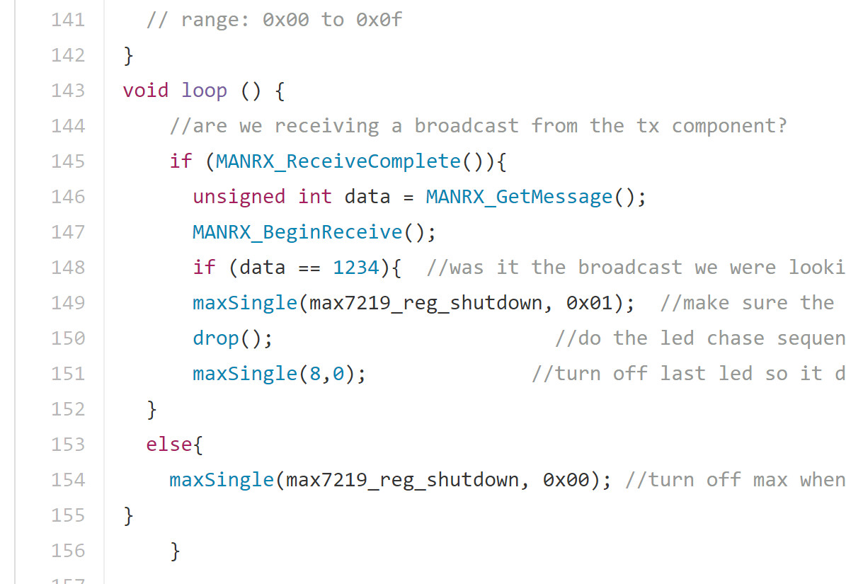
Here's a code snippet from the display side of things. Notice it just loops over and over waiting to see if a message has been received. There may be a much more elegant way of doing this with a software interrupt, but I never figured it out. My initial plan was to just have it as an interrupt every the time the receiver gets a logical '1' on it's receive pin, which would also have allowed for lots of battery saving low power options. Unfortunately this did not work because the receiver gets a lot of noise and constantly thinks it's going low or high. Sending a proper message involves lots of training bits (patterns of 1's and 0's that say, "yes, this is actually a message"). You can look up Manchester encoding for more details on that.
Also notice my truly unforgivable lack of proper code indenting. I was a much less experienced programmer when I wrote this.
It's also worth talking about how the display's atmega chip talks to the Max7219 led driver. As is true with everything else in this project, I hardly reinvented the wheel here, and I made use of lots of examples like
this one to get started. There are libraries for using Max72xx chips in arduino projects, but in my implementation I just shifted all the bits out in my code.
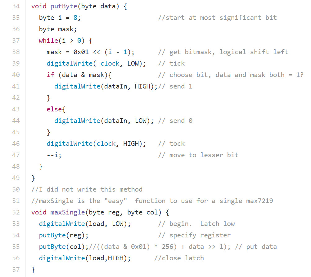
Sending serial data to a shift register or whatever, in this case the Max7219, with a microcontroller is pretty funny. You actually Use a pin to set the latch low, then shift a byte in one bit at a time while also setting the clock signal low and high for each bit, and finally set the latch high again.
In the maxSingle() function, you can see how we write data out by selecting a register and the value to be written to it. You can't get much closer to the metal than that!
Getting the Code onto the Chips
This segment doesn't cover the Arduino bootloader or Arduino support for the attiny85, and again I refer you to the High-Low Tech Attiny 85 tutorial, and the Sparkfun bootloader tutorial to help you with this. For me, this was definitely a hurdle in and of itself.
To get the code onto the chips, I used my Arduino Uno as the programmer. There is lots of material out there for how to get this done, and the code to make your Arduino function as a programmer is included as a sketch example called ArduinoISP when you download the IDE.
There were a few things I had to do to get the programmer to work though. I've never been able to load code to a device from the IDE itself, and instead I've always had to use avrdude from the command line. This is not exactly an intuitve process, and this tutorial from ladyada.net is a great place to get started figuring it out.
Another thing that I highly recommend is to change the baud rate in the ArduinoISP sketch. Look for the setup function and around line 69 where it says:
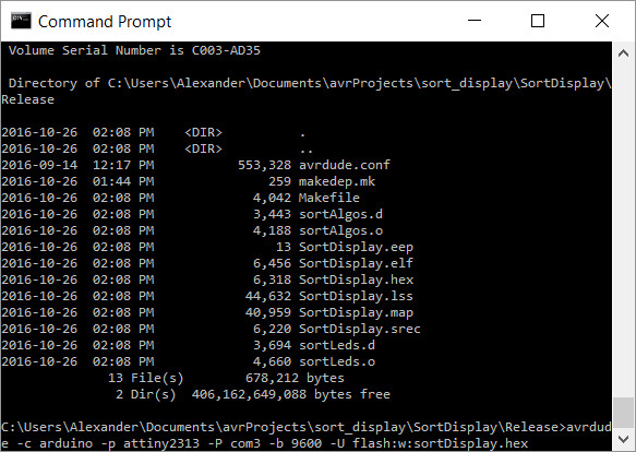
An example of using avrdude from the command prompt for another project.
It took a lot of trying different things and following different tutorials to get to the point where I actually had the Arduino bootloaders on the chips and I could flash my programs to them. It's a fantastic skill to have in my toolbox as an artist/computer guy/huge nerd, but man, it took some doing to get there.
Making the Display
 The display in progress
Always keep safety in mind whenever you're around power tools.
It was very important to me to have a very clean and somewhat minimalist aesthetic when building the display component. I am very lucky to have access to a table saw and a drill press to help me achieve this. Thanks, Mom and Dad!
Unfortunately I don't have any pictures of the machining, but it's fairly straight forward to describe. As you can see in the images, the main idea was to float a transparent piece of acrylic above and opaque white sheet of slightly larger dimensions. I had never worked with acrylic before, but it turned out to be pretty fun. The main trick is not to melt anything. Acrylic sheet stock typically comes with a protective film on both sides, and your end result will look a lot better if you just leave it on until you assemble the pieces.
Sawing
A table saw was used to get clean cuts as I cut everything to its final dimensions. An extremely important point is to use the correct kind of blade; using something like a cross cut lumber blade would probably destroy the acrylic stock and would likely be very dangerous to the operator! Because acrylic will melt pretty quickly with the friction of a saw blade, I found that the cleanest result was achieved by cutting in three passes, first on one face, then flip the piece over to cut a shallow pass on the opposite face, and finally the third pass separates the now barely joined pieces. Once the two main faces were cut to dimension, I adjusted to saw's angle to 45 degrees and carefully cut a bevel on each edge of the transparent piece.
You can see the bevel in the transparent piece that was cut on the table saw. It floats above the white piece by sitting on top of the four transparent acrylic cubes.
Thrilling stuff.
Drilling
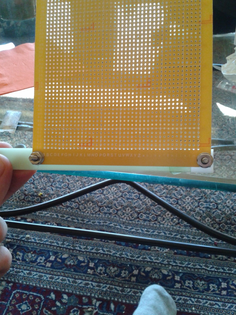
Because the leads of each LED had to pass through holes drilled into both the clear and white sheets, it was important that the drilling be as precise as possible. To ensure this, I used Adobe Illustrator to make a drilling template which I printed out and used a glue stick to attach a copy to each side. Given that the two sheets were slightly different dimensions, it was important to center the templates on them as close as possible. I just used a ruler.
I learned a couple of tricks for getting great results drilling acrylic. First of all, having a drill press was a help, as it guaranteed perfectly straight holes each time. Another great tip is to go very slowly. If you give too much pressure with the drill, the bit will tear through the acrylic at the end and put ugly cracks in the acrylic. Lastly I saw a great tip on the internet some where to cool the drill bit with baking soda mixed into water. The water keeps everything cool (again, pretty easy to melt it while drilling, which looks ugly) while the baking soda prevents the water from rusting up the metal components the water comes in contact with. I'm not a chemist, and I don't really understand what's involved, but apparently sodium bicarbonate stops metal from oxidizing. I also suspect that the baking soda acts as a cutting agent to keep the holes smooth, which they certainly will be if you do everything well. I guess you could have some kind of great setup with a drip bottle or something, but I always just drilled a little divet, filled it up with the coolent, and finished the hole. I kept the drill speed on the low side, and occasionally wetted the bit down to disperse heat. The result was worth the trouble.
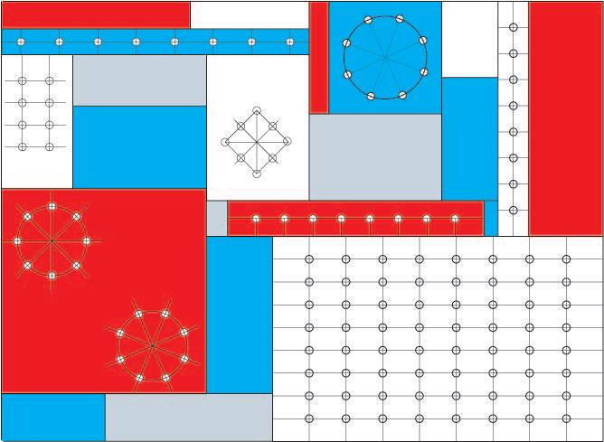
The first image is a drilling template I made for a similar project. The one used here was more like just the lower right grid part.
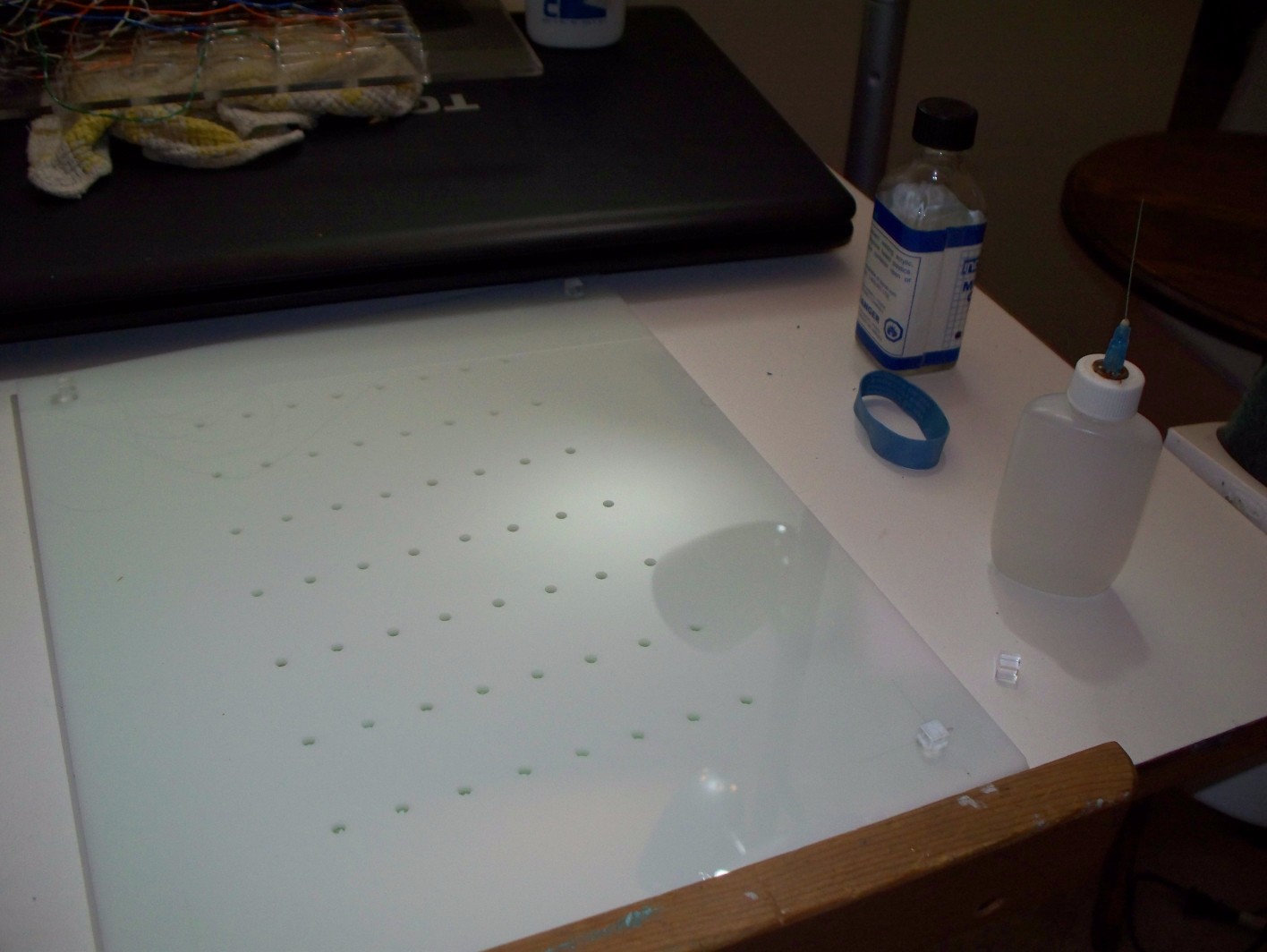
Also shown is the transparent top piece, all milled with the stand-off cubes. You can also see a glass bottle of methylene chloride, which is the solvent used to attach the acrylic pieces together.
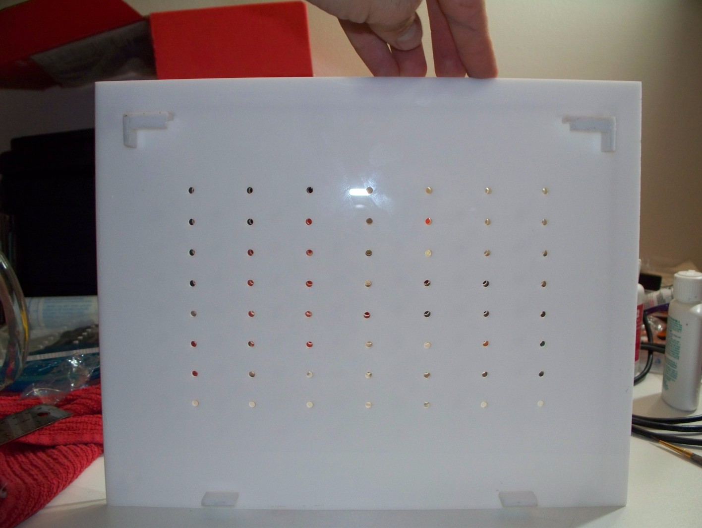
The last image is a view from behind with the two faces attached together. I attached tabs as a stand-offs to keep the electronics from touching any surfaces.
With all the milling done, it was time to assemble all the pieces together. If I recall correctly, I used paint brushes that would fit through the 5mm holes to keep the two faces lined up perfectly while they were attached. Acrylic is typically joined using a solvent called methylene chloride, and it makes a strong bond if everything is done properly. There're countless instructions on the internet for working with acrylic, and I won't ramble about the details. In one of the pictures above you can see a syringe bottle that I used to apply the solvent, and doing it this way works great, but lately I've been preferring to use a small paint brush instead. The solvent is far thinner than water, and all that's needed to make a good join is to place the two pieces together, and apply a little solvent to the seam. Capillary action is sufficient to make sure both adjoining faces get coated in solvent and bond well.
Installing the Electronic Components
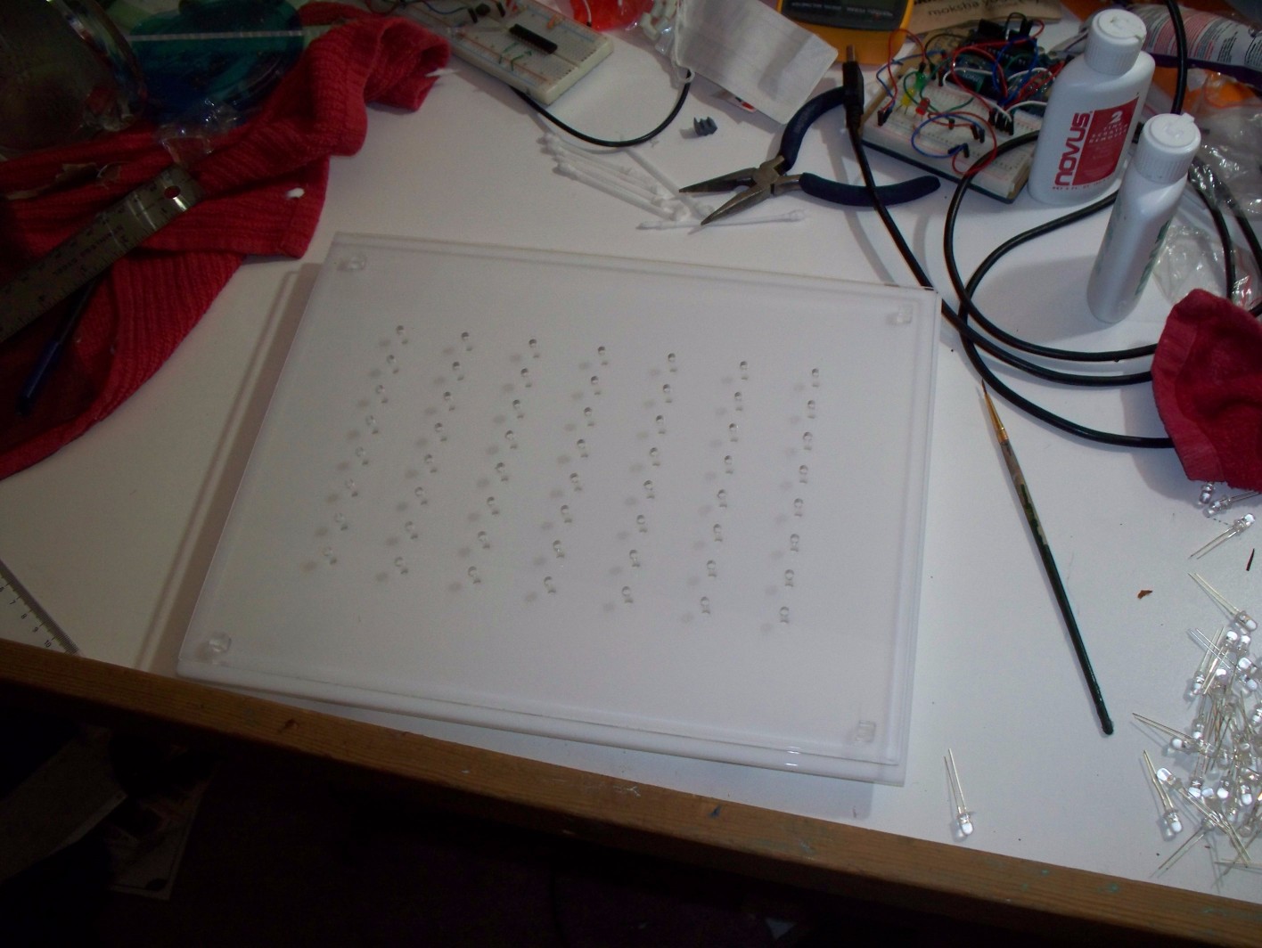
By this point the code was working and flashed to the chips, the devices were shown to work properly on a breadboard, and most of the acrylic work was done, so I could finish up. The first thing was to attach all the LEDs. When making the first matrix display that I ended up not using, I had read a bunch of very bad advice about how to fix them to the surface. In short, use epoxy glue. It's the only thing that really works, and it works really well. They each went in the same way with about a quarter turn to make sure that the anode and cathode of each one would not touch when the leads were bent into position. Check out the images below to see what I mean.
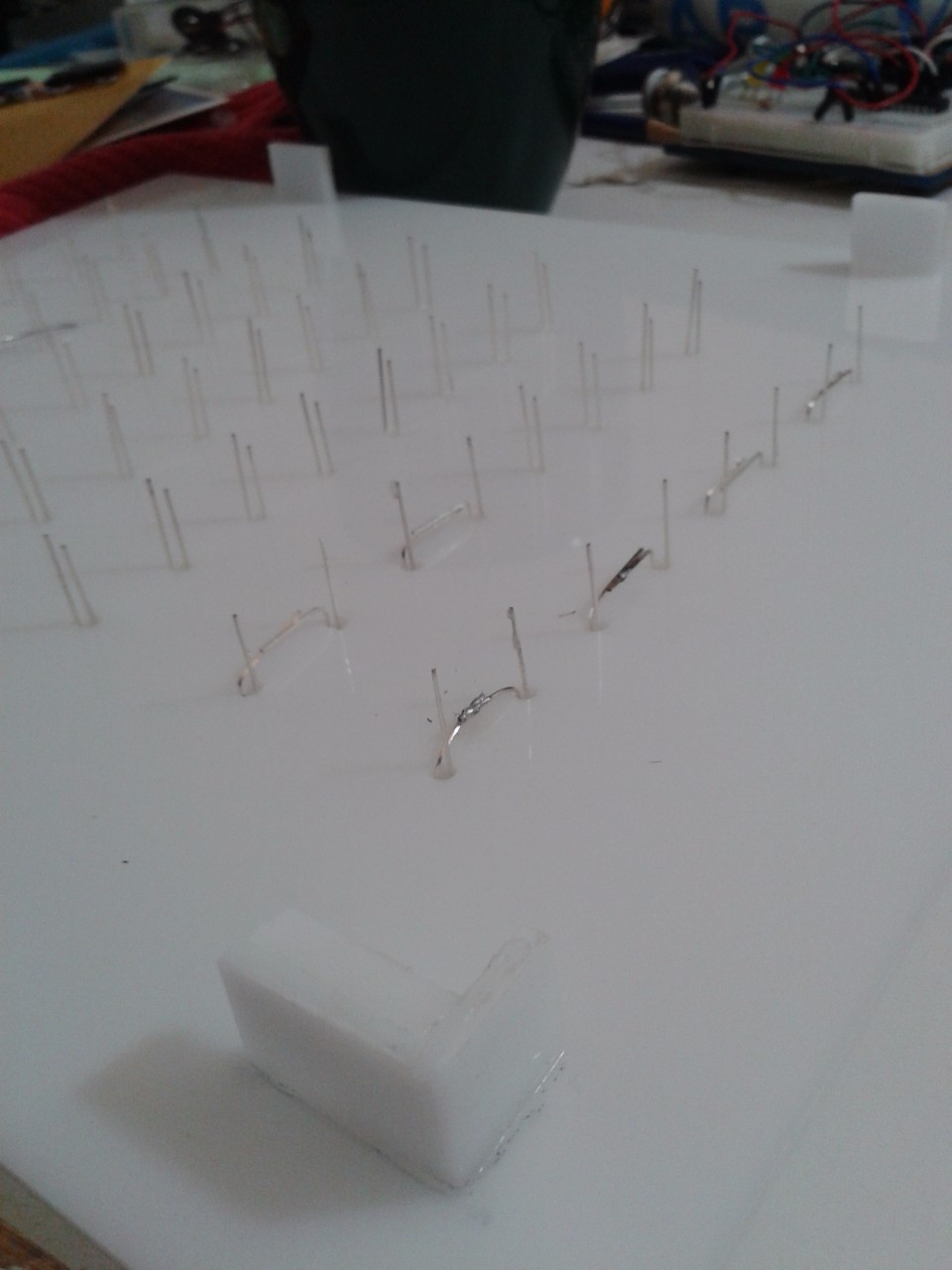
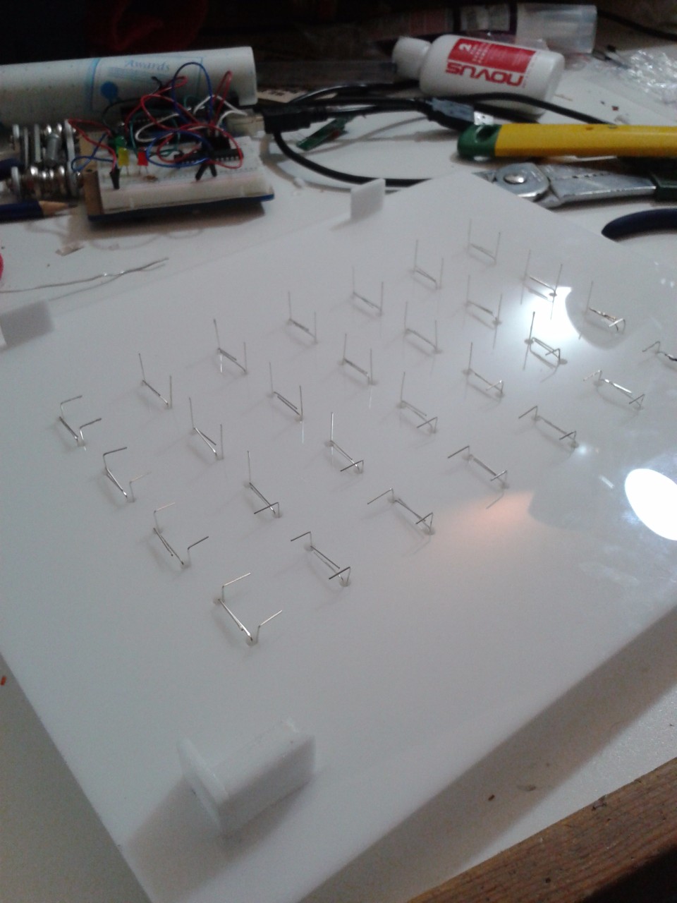
The LEDs have all been glued to the surface, and get their leads bent for soldering. To work with the Max7219 driver, the LEDs are common anode by column, and common cathode by row. We can use the Max7219 to address each LED by its row/column index.
Not shown here is that I had to jumper the gaps where leads couldn't reach their neighbour with some extra wire. It was lots of soldering.
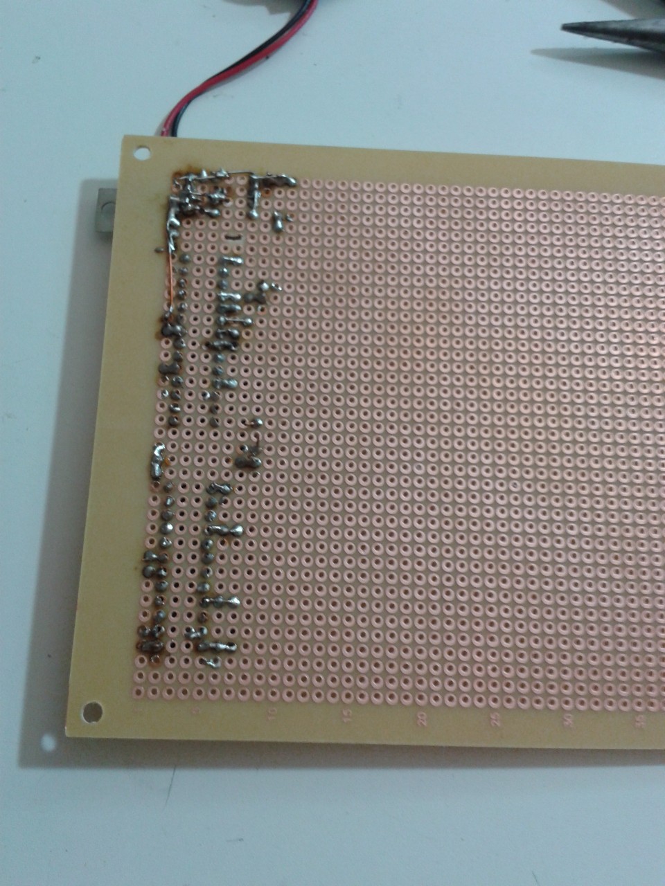 All the soldering done for the display component. You can see the top of the linear volage regulator that I evently swapped out peeking out.
 To secure the protoboard onto the display, I bolted it to a piece of acrylic. The bolt heads were counter sunk beneath the surface, so the acrylic could be attached to the rest of it.
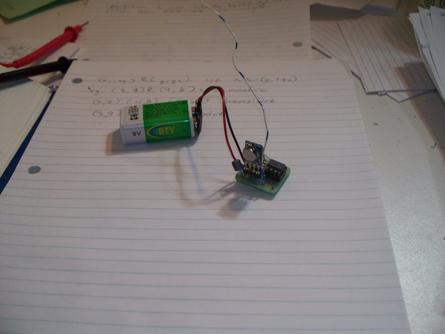 The sensor without the piezoelectric element yet.
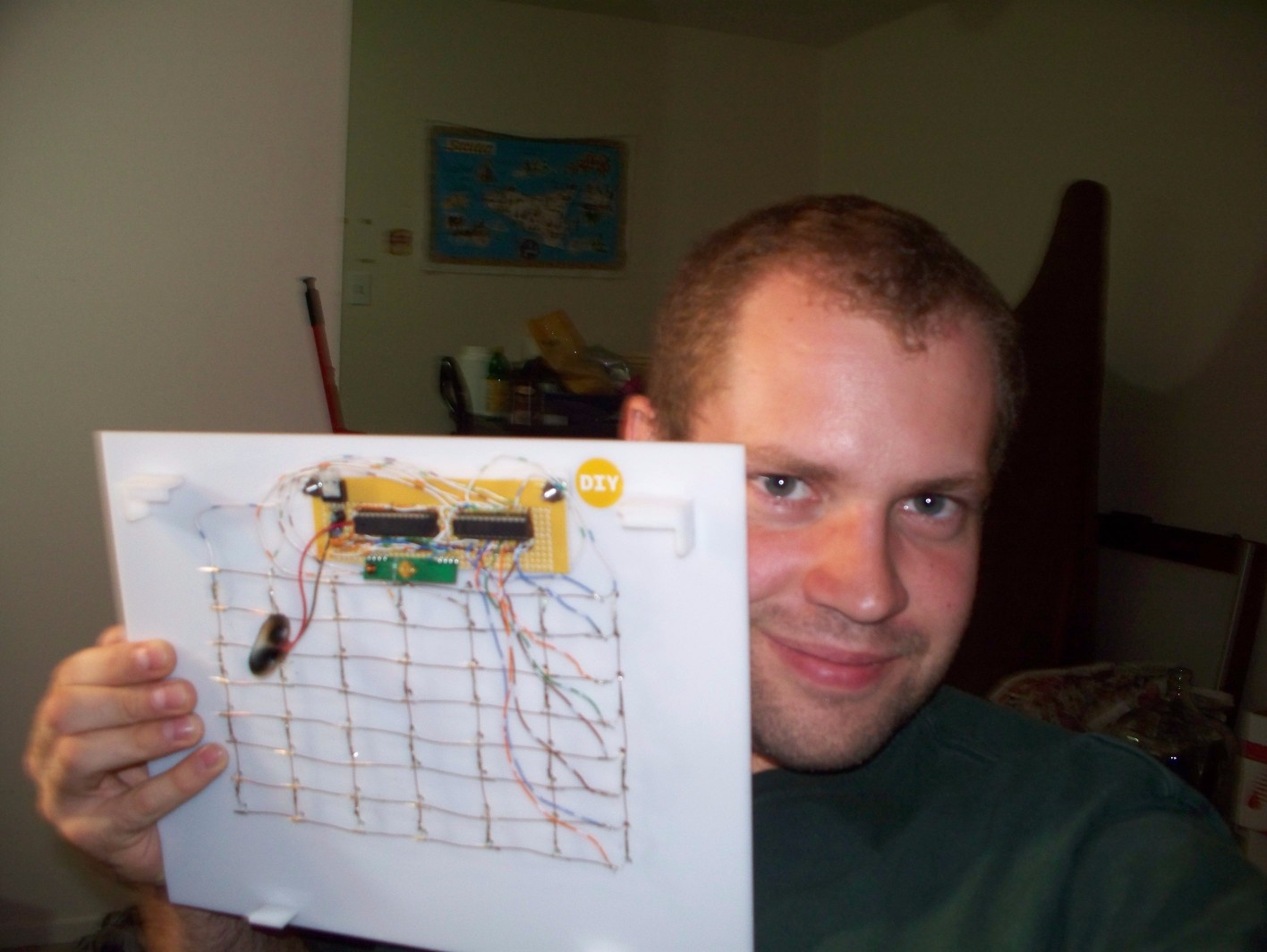 A very happy Alex-From-Four-Years-Ago takes a selfie with his finished work.
It's Done!
It was a cool project and intensely rewarding to see it all working in the end. I started on it after my first year of my computer science degree, so like sometime in 2011. It wasn't an entirely easy process, and I had a lot to learn on the way. It may sound cheesy, but it's really my first programming project that I did out of my own interest, and I certainly grew as a programmer making it. It's also a monument to persistence; this project took ages and was placed on the back burner more than once as school semesters got busy, etc.
I'm very proud of it. It's hardly a ground breaking invention or anything, and I hardly can claim that it's all my work as it relies on software libraries and examples from others. None the less, I think it's a valuable ability for a programmer to visualize what they want to accomplish, and then worry about the how. I think it's easy to get into a mind frame where the how directs your production. As my Mom once said, and I fully agree, that the biggest thing in programming is to know what is possible, and learning how to accomplish it can then be secondary.
Last but not least, I'm pretty sure that having my own projects like this one outside of course work was a key factor in getting hired by my co-op job during university, which has been one of the best experiences of my life.